| ProLinga Tutorial |
|---|
Since we have made a screen before, not all steps are described in great detail. If you have problems understanding it, you may want to go back and re-visit earlier chapters.
To build a Data Entry Screen, open the application in the ProLinga Developer and go to the Screen Dialog Editor. Click the toolbar button "New Window" and then save this screen with the name "Device". Now bring it up in the painter.
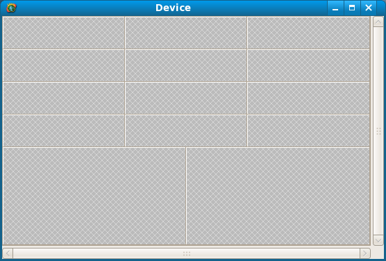
Set the window title to "Device", set the width to 550 and the height to 350.
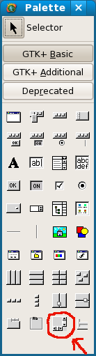
Remember the screen "Main" where we placed a "Frame" object in the third section. In later exercises, we will learn how we can integrate the screen "Device" with the screen "Main". To make this possible, we first have to place an object "Scrolled Window" on our screen "Device".
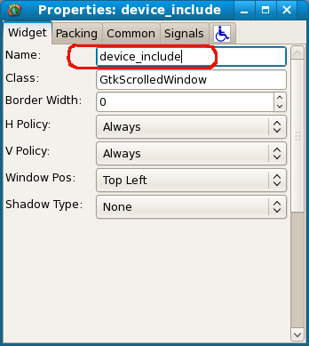
Go to the properties screen of the scrolled window object and give it the name "device_include".
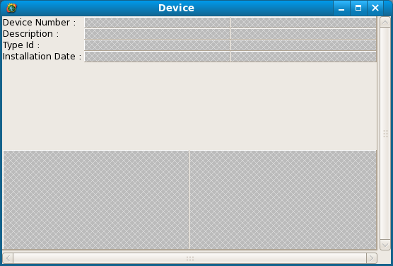
Within the scrolled window, place a "Vertical Box" with 2 rows. In the first row place a painter object "Table" with 4 rows and 3 columns. In the second row place a "Horizontal Box" with 2 columns.
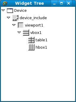
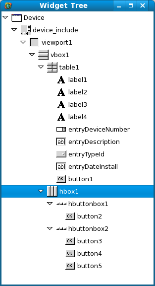
Once we are placing objects within objects, it is easy to get lost. Therefore you can open a widget tree window. In the painter go to pulldown menu "View" and then click option "Show Widget Tree". Here you can simply select any object that you have placed on the screen.
We have 4 data dictionaries in our table definition "Device". We can now place an object "Label" on the screen for all 4 of them.
Do not worry about the layout. Once all objects are on the screen, we will get all objects to display right.
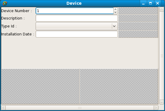
In the next column we put the object "Spin Button" for the Device Number field, since that is a numeric one, "Text Entry" for the Description field, "Combox Box" (not be confused with Combo Box Entry) for the Type Id field and "Text Entry" again for the Installation Date field.
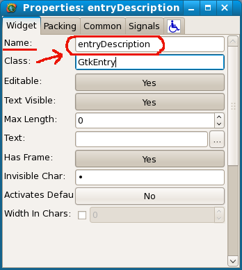
It is important to give all the editable objects a name, so we can refer to it from ProLinga logic. Use the names "entryDeviceNumber", "entryDescription", "entryTypeId" and "entryDateInstall". These values can be set in the properties screen of the objects as the example below of the Description Field shows.
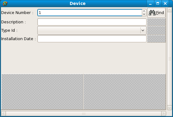
In later chapters we want to create a lookup screen for the Device Number field. That means we have to trigger an action. For now we will just place a Button on the screen called "Find".
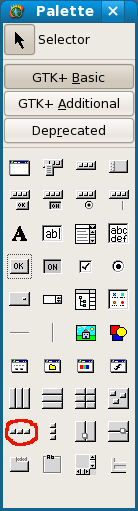
In the bottom 2 sections we are going to put a "Horizontal Button Box" in both of them.
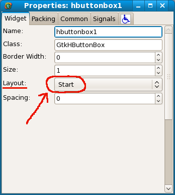
When asked for the number of buttons in the box, type 1 for the left one and 3 for the right one. Then go to the properties screen of the left button box and set the value "Layout" in the "Widget" tab to "Start" and set the value to "End" in the right button box.
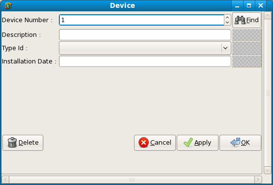
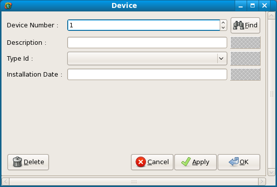
Now set the left button to be a "Delete" button, and the other 3 to be "Cancel", "Apply" and "OK". Your screen "Device" now should look similar to this.
All objects that we want to have are on the screen, so now we can format the screen to look a bit better. The buttons should always be at the bottom of the page. So we have to prevent them from expanding. The 2 horizontal button boxes are child objects of the horizontal box object, so we need to go to the properies screen of the horizontal box object. This is where you want to use the Widget Tree screen.
Select the horizontal box object in the Widget Window and go to the properties screen. There under the tab "Packing" you will find a setting called "Expand". Set this to "No". You will see the direct effect in the "Device" screen in the painter.
The rows and columns are a bit close to eachother in the screen and we should add some spacing. The labels and entry fields are child objects of the table object. Select this object in the Widget Window, go to the properties screen and select tab "Widget" (Default). Set both Row as Col Spacing to 5. Set the field Border Width of the vertical box (vbox1) to 10. Your screen now should look similar like this in the painter.
The unused spaces around the "Find" buttons, will look OK at run-time.
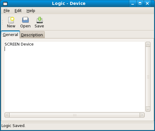
Before we can test this screen at run-time, we must remember how we are calling this screen. From the pulldown menu and toolbar, we created an action handler L-Device, meaning call logic "Device". We have not written that logic yet, so it is time to do it now. For the time being, all we want this logic to do is to call screen "Device". Therefore, open the Logic Editor in the Developer and write the following logic:
SCREEN Device
Save this logic and name it "Device".
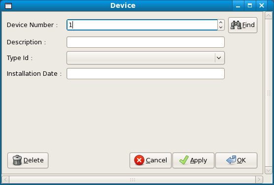
Start your application and see if the "Device" screen comes up. We have not written any logic yet to read/write data from/to your database, so that part will not work yet.
You will notice that if you run your application your Device screen comes up as a separate window as soon as you select the pulldown menu option "Device".
In a previous exercise we created a frame called "frame_main" on the screen called "Main". What we want now is to project this new Device Screen into this frame, so it becomes one single screen. To cater for that we have to go into the ProLinga Developer and open logic "Device" in the Logic Editor. Now we change the logic from:
SCREEN Device
to:
SCREEN Device CONTAINER frame_main SOURCE device_include
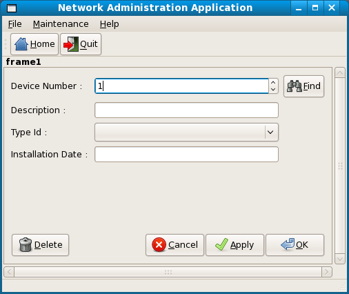
This tells the run-time engine to get from the screen "Device", only the object "device_include" and child objects. This "device_include" is the scrolled window object that we placed on the screen "Device". This "device_include" then should be projected in the frame (or often called containter) "frame_main" on the current screen. Save this logic and if you now run your application, you should have a similar screen as below, once you click on the "Device" pulldown menu option.
As you will see the screens are nicely merged into a single screen. If it is not working, please review previous exercises where we placed the frame "frame_main" on the screen "Main" and where we created the scrolled window object "device_include" on the screen "Device".
As all following exercises continues to work with this merged view, do not continue until you have it working.
| << Create a Table | Create Picklist >> |